The Key To Ignition Troubleshooting
The Key to Ignition Troubleshooting
Part I: The Basics
Len Vucci
YEAR AFTER YEAR, the cost of motorcycle maintenance rises. More complicated machines are one reason. Rising labor costs and increased shop overhead are others. If you continue taking your bike to the dealer for service, there is absolutely no way to fight it. There is, however, an alternative. Do the work yourself.
If you’ve never lifted a wrench before, the idea of tuning up a motorcycle unassisted is scary. But take it from us, it is not impossible. In fact, if you have command of the basic principles and some detailed instruction, you can be just as successful as the dealer your first time out.
About this time you're probably saying, “Sure, but I don’t have the tools.’’ That may be true, but look at it this way. If you have a four-cylinder machine, the cost of tools needed should only slightly exceed the labor cost of a tuneup.
But that's only for the first tuneup. After that you'll be money ahead. If you’re interested in specifics, we just had a Z1 serviced and labor on the tuneup portion alone was $36. That’s $36 you'll never have to pay again if you do your own work.
There are basically three separate areas dealt with in every tuneup. The first is chassis lube. Here the swinging arm pivot is greased, the rear chain is adjusted and oiled, and the engine oil (and filter on some models) is changed. Second is basic engine mechanical adjustment, in which carburetors are synchronized and valves adjusted. Last, and perhaps most troublesome, is ignition adjustment.
In upcoming months, CYCLE WORLD will present do-it-yourself articles on all three tuning phases. But for now we’re going to concentrate on ignitions. This article will deal with an explanation of how the various types of motorcycle ignitions work, the components involved, etc. We feel this information is essential in making your first ignition tune a success.
IGNITION CONSIDERATIONS
In order that an understanding of the various types of electrical ignition systems be realized, one must first be familiar with the basic operations of a simple internal combustion engine.
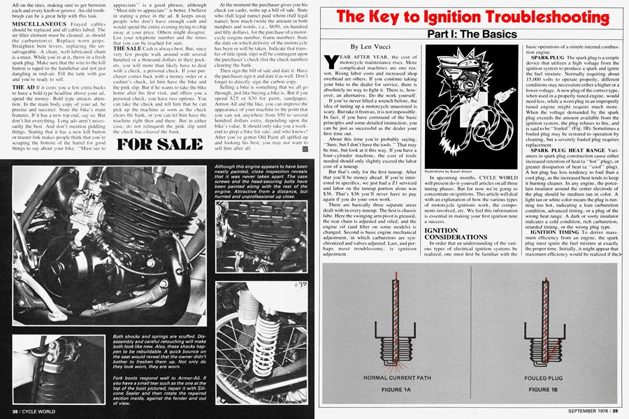
SPARKPLUG The spark plug is a simple device that utilizes a high voltage from the ignition system to produce a spark and ignite the fuel mixture. Normally requiring about 15,000 volts to operate properly, different conditions may necessitate either a higher or a lower voltage. A new plug of the correct type, when used in a properly tuned engine, would need less, while a worn plug in an improperly tuned engine might require much more. When the voltage demanded by the spark plug exceeds the amount available from the ignition system, the plug refuses to fire, and is said to be “fouled” (Fig. IB). Sometimes a fouled plug may be restored to operation by cleaning, but a severely fouled plug requires replacement.
SPARK PLUG HEAT RANGE Vari anees in spark plug construction cause either increased retention of heat (a “hot” plug), or greater dissipation of heat (a “cool” plug). A hot plug has less tendency to foul than a cool plug, as the increased heat tends to keep it burning cleaner. In any engine, the porcelain insulator around the center electrode of the plug should be medium tan in color. A light tan or white color means the plug is running too hot, indicating a lean carburetion condition, advanced timing, or a plug of the wrong heat range. A dark or sooty insulator indicates a cold condition, rich carburetion, retarded timing, or the wrong plug type.
IGNITION TIMING To derive maximum efficiency from an engine, the spark plug must ignite the fuel mixture at exactly the proper time. Initially, it might appear that maximum efficiency would be realized if the> spark occurred at the moment that the piston reached the top of its travel in the cylinder (top dead center, or TDC), (Fig. 2A). This is not the case. Because the fuel mixture does not burn instantaneously, the piston will have traveled back down somewhat before pressure builds up sufficiently. Since any additional delay in timing (as would occur if we caused ignition after top dead center, or ATDC), (Fig. 2B), results in an even slower buildup of pressure, it is immediately apparent that ignition should occur before the piston reaches top dead center, or BTDC (Fig. 2C), in order that pressure will have sufficient time to build to a usable level.
ADVANTAGES OF PROPER TIMING
By igniting the fuel mixture at the proper point (BTDC), several benefits are realized:
1. Increased combustion chamber pressure, producing more power.
2. More complete burning of the fuel mixture, with less unburned fuel escaping out the exhaust.
3. Increased “thermal efficiency.” This means that more of the heat produced by combustion is converted to mechanical energy, and less heat is wasted by increasing cooling system temperature. It is for this reason that a retarded state of ignition time, even though resulting in lower combustion chamber temperature, tends to cause an overheated engine.
We must introduce one other variable in ignition advance: the effect of engine speed on burning time. If we double the rpm, the fuel mixture has only half the time in which to complete its combustion. If the timing is set for low-speed operation, high-speed operation will suffer, and vice versa. Many motorcycles are timed for the rpm range in which they are primarily operated, usually the top end. But many bikes, and nearly all cars, have the ability to vary the amount of ignition advance as a function of engine speed: low rpm —less advance; high rpm —more advance. This “dynamic” advance, usually combined with some fixed or “static” advance, allows a greater degree of thermal efficiency over a broader rpm range, and, hence, improved performance.
TYPES OF DYNAMIC ADVANCE
There are three types of dynamic advance:
1. Vacuum advance, which is used mainly on auto engines and will not be discussed here.
2. Centrifugal advance, which is used on auto and motorcycle engines. This is a mechanical system that causes the ignition to advance beyond the initial (static) timing advance setting (see Fig. 3). If an engine has 10° static advance at idle speed, as the rpm increased to a certain point —let’s say 1000 rpm—the timing would stay the same: 10°. But as speed was increased farther, advance would also increase, up to the limit of the advance mechanism. If the upper limit of our advance was an additional 20° at 3000 rpm, then at 3000 rpm the total advance would be 30°. In between 1000 and 3000 rpm the total advance would be between 10° and 30°, varying approximately with engine speed. Beyond 3000 rpm, the advance would still remain at 30°, the limit.
3. Electro-magnetic advance as a function of rotational speed. On some types of CDI (capacitor discharge ignition) systems—usually those that do not require a battery for ignition operation—the inherent properties of the components involved will cause ignition advance over most of the rpm range. The amount of advance will vary from bike to bike, but unlike centrifugal advance, which can be modified to change timing characteristics, electro-magnetic advance is predetermined by the design of the CDI system. If the engine is running, EM advance is also okay and not to be worried about.
BATTERY/POINTS IGNITION
In this type of system (used in XL 125 and 175 Hondas, for example), sometimes called “conventional ignition,” low voltage (usually 6 or 12 volts) is used to produce the necessary spark plug voltage (15,000 volts and higher). The procedure is very simple and has much in common with the more sophisticated electronic (CDI) and magneto systems. The device that actually steps up the “primary” 6 to 12 volts to the spark plug voltage is the coil (technically a step-up transformer). (See Fig. 4A). The output of the coil is connected to the plug and to ground (from here on think of ground as being a single wire, although, in reality, it is all the interconnected metal parts of the bike). High voltage will only be produced in the output side under a single condition: there must be a sudden change of electrical current in the input side of the coil. This can be achieved by closing switch “S,” which would instantly apply the battery voltage to the coil primary (Fig. 4B). From the secondary there would be a surge of current and a spark at the plug. Leaving the switch closed, there would be no spark after the initial one, as the current in the primary side of the coil would have stabilized. If the switch were now opened, current in the primary would abruptly cease to flow. The coil primary has just felt another sudden change of current and the coil secondary has produced another spark.
Simple? Add one additional component and you’ve got the total ignition system of a single-cylinder engine. That component is the condenser (also called the capacitor), which is wired directly to the switch. In actuality, the switch is a set of contact points (Fig. 4C). The condenser serves two important functions. By its ability to conduct swift changes of current, it prevents a severe spark from occurring across the contact points as they open, keeping them from becoming burned and pitted. This conduction of current as the points open—because of the electro-magnetic properties of the coil-will make the spark felt at the plug much stronger. Understandably then, it is the high voltage produced as the points open that will be used to ignite the fuel in the engine. If the condenser were disconnected, or its wire broken, there would be a very feeble spark, if any at all, at the plug. When the points close in a normally operating system, another very feeble (if any) spark may occur at the plug.
MULTI-CYLINDER BATTERY/POINTS IGNITION
Multis utilize the same basic system outlined above in two different ways. Some (for example, Yamaha XS750, Suzuki Triples, Kawasaki Triples without CDI, Honda CB350/360), utilize a set of points, a condenser and a coil for each cylinder (Fig. 5). Operation of each individual circuit is independent, and is identical to that of the singlecylinder system. Others (Honda GL1000, CB400/500/750, Kawasaki KZ900/Z1, KZ400, for example), utilize one set of points, one condenser and a dual output coil to provide spark for two cylinders (Fig. 6). It’s an ingenious method to simplify construction without sacrificing quality. Both of the cylinders connected to the coil fire simultaneously. At first it seems that continual misfires would occur, but for a simple reason they do not. While one cylinder utilizes the spark to ignite a charge of fuel, the other cylinder is at the top of its exhaust stroke, about to draw in a charge of fuel (remember that these are all four-stroke engines), and the spark has absolutely nothing to ignite. The simplicity of the operation is impressive.
MAGNETO/POINTS IGNITION
The magneto/points ignition system (used in Yamaha DTI, RT1, DT250, and the Honda MR250), is nearly as simple in theory as the battery/points system, and when set up properly is very reliable. Its main difference is the method used to provide electric current to the primary winding of the coil. For this, a magnet (from which the name of this system is derived) and a coil are used. In principle, whenever a magnetic field is moved across an electrical conductor, an electric current will flow. In application, a coil (electrical conductor) is mounted on the crankcase and a strong magnet, cast into an aluminum flywheel, passes by the coil as the engine rotates. This sets up in the coil an electric current that may approach several hundred volts (Fig. 7). This buildup of current does not happen instantaneously, but starts off low, reaches a peak as the magnet is directly adjacent to the coil, then begins to decrease.
This is the voltage that will be applied to the primary of the ignition coil to develop the high-voltage spark at the plug. To accurately control the firing point, a set of contact points and a condenser are inserted across the magneto coil and perform much the same function as in the battery/points system (Fig. 8A). The points remain closed until the magnet is adjacent to the magneto coil —at which time current has built up to a maximum—and then are allowed to open (Fig. 8B). The current, which had been shorted to ground by the points, now surges into the primary of the ignition coil, producing a high voltage in the secondary and a spark at the plug.
A “kill” switch, normally open for engine operation (Figs. 8), is also wired across the points. When closed, it acts as though the points never open, effectively keeping magneto coil current shorted to ground and disabling the system.
An obvious advantage to the magneto system is that a battery is unnecessary for ignition, though some bikes retain a battery for lights and horn, using an additional magneto coil in the charging circuit. A performance advantage is realized by the inherent properties of the magnet/coil generation of electrical current: as the velocity of the magnet/conductor interaction increases (i.e., an increase in engine speed), the electrical output increases also. In basic English, the faster the engine, the hotter the spark, just the opposite of conventional ignition systems.
CAPACITOR DISCHARGE IGNITION (CDI)
Any time that parts of a product subject to wear are replaced with components that aren't, the product is usually improved. CD ignitions are typical in this regard. In the preceding types of systems, the weak points were just that: the contact points. Keeping point-type systems in proper tune requires periodic maintenance. Period. CD ignition, if not damaged by physical contact (testing the law of gravity, for example), or operator/ tuner abuse, should be virtually maintenancefree. Other advantages include a hotter spark (30-40,000 volts, twice as high as pointtypes), more accurate ignition timing, and ease of adjustment (rarely, if ever, necessary) .
BATTERY/CDI
Used in some Kawasaki HI models, this type of CDI was one of the first. It can be thought of as having two distinct subsystems: a primary voltage developer and a trigger circuit (Fig. 9A). The 12 volts of the battery are stepped up to approximately 400500 volts DC and are used to charge up a capacitor. (A capacitor, or condenser, as it has been called when referring to point-type ignitions, has the ability to store up electrical energy. One may think of it as a very tiny battery, easily and quickly charged, easily and quickly discharged). This capacitor is connected to the primary side of the ignition coil, and both are now in a “ready to fire” state. Connected to the crankshaft of the engine is a rotating magnet, which causes a current to flow in a small coil mounted close to it (actually a miniature magneto). This is called the signal generator. At the appropriate time, the signal generator sends a small pulse of current to the trigger circuit, which effectively becomes a direct short circuit between the fully charged capacitor and ground. This causes the capacitor to discharge very suddenly to ground, and a large current surge is felt in the primary of the ignition coil. As with the other types of systems, the result is a very high voltage in the secondary and a spark at the plug (Fig. 9B).
In the Kawasaki HI with CDI, there is but one of these systems. Additionally, the signal generator contains three individual magnets mounted 120° apart, causing the CDI system to fire three times for each revolution of the crankshaft (Fig. 10). There is also a distributor on the other side of the engine that receives the three high-voltage pulses from the ignition and directs one pulse per revolution to each of its three cylinders.
(Continued on page 86)
Continued from page 43
MAGNETO/CDI
Analogous to the magneto/points ignition, magneto/CDl needs no battery to provide a spark. Fast becoming the standard on many off-road bikes (Yamaha DT360 and YZs, Suzuki RMs and TMs, Can-Ams, models that use Femsa and Motoplat systems, Kawasaki KX250) and some street machinery (like the Suzuki GT500 and Kawasaki H2), it leaves little to be desired.
Rather than use a battery to develop the several hundred volts needed to charge the capacitor, this system uses a magneto and a circuit called a rectifier (Fig. 11). (The term diode is sometimes used interchangeably with rectifier. but diode refers to the actual electrical component, while rectifier usually refers to the electrical function). The purpose of the rectifier is to ensure that the capacitor stays charged until the trigger circuit can fire. Without the rectifier, the capacitor would charge as the magneto current was on the rise. Then, as the magnet passed by the coil and magneto current began to decline, it would draw' the charge back out of the capacitor, rendering the system inoperative.
Restating the previous actions, the magneto and rectifier have provided approximately 400 volts DC, which charges the capacitor connected to the ignition coil (Fig. 1 1).
At this point the operation is identical to that of the battery/CDI system. A small pulse from the signal generator is fed to the trigger circuit, which provides an electrical path from the capacitor to ground; the capacitor discharges abruptly, causing a current surge in the primary of the ignition coil and producing a high voltage in the secondary and a spark at the plug.
One additional configuration we must add to this section is that of the Kawasaki H2. This consists merely of three of the above systems (one per cylinder), sharing only the flywheel magnet (to energize the three magneto coils), and the signal generator rotor to pulse each trigger circuit once per engine revolution. The signal generator coils are mounted 120° apart, as are the magneto coils. As one might surmise, the cylinders fire at 120° intervals.
CAUTIONS TO BE OBSERVED
There are several important points to remember when working around ignition systems. The most critical concerns the proper care of CDI components, as many malfunctions are the direct result of unintentional abuse. Never attempt to operate the ignition system without a proper load on the highvoltage lead, especially with a CDI. The normal load is a spark plug, which serves to limit output voltage to its proper level ( 15,000 in a conventional ignition, 30-40,000 volts with CDI). When either system is operated without a load, the voltages produced in the coil may exceed these values tremendously; damage to the system is a very real possibility. Always ground the high-voltage lead when cranking the engine without a properly connected plug. Always make sure that electrical connections are clean, dry and tight, because a poorly made connection can kill an engine as effectively as a rod through the bottom end. So can a frayed wire leading to the kill button, Inspect it along its entire length if possible.
ADHERENCE TO MANUFACTURERS’ SPECIFICATIONS Should one wish to deviate from factory timing specs (normally not advised), a certain amount of care should be exercised to avoid damage. Excessively advanced timing can induce a condition called “detonation,” which, because of increased combustion chamber pressure and temperature, can cause unburned pockets of fuel to self-ignite independent of normal> ignition. Severe shock waves are produced, and may be violent enough to cause physical damage to the engine. Also called “pinging" or “knocking," detonation is normally audible, but may be masked by a loud exhaust pipe.
Continued from page 87
PRE-IGNITION Similar to and often confused with detonation is “pre-ignition." And, in fact, one may cause the other. Preignition is a condition whereby the fuel mixture is ignited before any spark occurs, and is the result of an excessively hot combustion chamber condition. This may be caused by a general overheating problem such as loss or blockage of cooling system fluid, or inadequate air flow over cooling surfaces. Since pre-ignition often ignites the mixture before the spark occurs, turning off the ignition may not stop the engine from running, a condition called “dieseling" or “run on."
Pre-ignition may also be caused by a buildup of carbon that remains hot enough between firing cycles to ignite an incoming fuel charge, by a too-hot spark plug, or by one of excessive reach that extends into the combustion chamber.
METHODS OF TUNING AN ENGINE
We have attempted in this article to describe and provide an insight into the basic theory of the several types of motorcycle ignition systems in common usage today. With this information you should be able to understand the basic processes occurring within the engine of your bike. Combining this knowledge with the actual procedures of tuning, which will be dealt with next month, the average reader should be able to affect a professional quality tuneup on his/her own motorcycle, providing the proper methods are adhered to.
Tools required will depend primarily on the type of ignition system and model of the specific motorcycle to be tuned. All will require basic hand tools. If not already owned, most of these can be purchased at a cost more reasonable than that of a shop tuneup. In some cases special tools will be necessary. For example, while the timing on some battery/point systems can be set accurately with a home-made test light, other models will require a power timing light and/or a dial indicator.
In any case, the outlay for tools is a minor expense compared to normal shop charges if required service is performed faithfully. What’s more important is that you will have the confidence and satisfaction that stem from a tuneup that’s been done right.