Troubleshooting Ignitions: Getting To the Points On Time
TROUBLESHOOTING IGNITIONS: GETTING TO THE POINTS ON TIME
Tools and Techniques For Doing It Right
Len Vucci
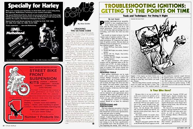
PROPER MOTORCYCLE MAINTENANCE is less complicated than it looks. Spend a few dollars for basic tools, plan the work before you do it, and follow instructions. You’ll save money, the work will be done right and perhaps the most rewarding, you’ll know the work was done right.
Last month we looked at theory: how the various types of ignition systems work.
This month we apply the theory, with detailed procedures for inspection and adjustment of ignition systems. Because there are different systems in general use, we’ll look at four different engines. They are:
1. Honda 750 Four, four-stroke, (battery/ points)
2. Suzuki 380 Triple, two-stroke, (battery/ points)
3. Honda 250 XL Single, four-stroke, (magneto/points)
4. Yamaha 250 DTI Single, two-stroke, (magneto/points)
Due to space limitations, CD ignition systems will be elaborated upon in the November issue of CW. As many tuning procedures are common to each of the different types of systems, CDI owners should also familiarize themselves with the methods outlined here.
REQUIRED TOOLS
Most ignition adjustments can be made with a few common tools: a spark plug wrench, Phillips screwdriver, medium adjustable wrench, set of feeler gauges, and homemade test light. If the original toolkit is still on hand, the frugal will invest less than five dollars. For some models, a dial indicator, volt-ohm meter or power timing light may be necessary. In that case, the fiver might swell to a fifty.
As this article progresses, specific tools will be referred to and approximate prices mentioned. More than one method may be given to attain a desired result, so costs incurred can vary with individual preference.
A comprehensive owner’s or workshop manual should be on hand for reference purposes.
SUGGESTIONS AND PRECAUTIONS
The most important precaution is knowing exactly what procedures you are to follow. One should have all necessary specifications, tools and parts prior to starting.
Determine existing settings before making changes. A prior check gives one a basis for comparison. If the engine has been running poorly and your inspection shows point gap and timing to be far from specifications, you probably know what the problem is before beginning the tuneup. And—which can happen—if the engine ran better before you did the work than after, you can return the settings to what they were before you made any changes.
The next thing before actually tackling the work is to make sure the bike is clean. This isn’t just being neat. The smallest particle of non-conductive material caught between the ignition points, for instance, guarantees that the ignition won’t fire and the bike won’t run. Dirt, grease, even lint from a shop rag can ruin an otherwise perfect tuneup. A 500 bath at the local car wash can make the whole job easier.
Is Your Bike Here?
Because there is no way to fully describe every motorcycle ignition, we’ve chosen a popular example of each common type.
For easy reference, the material on the Honda 750 Four also applies in general to the smaller Honda Fours, the Kawasaki Z1 and the Honda GL1000. Twins, like the Honda 360, Yamaha 360, Kawasaki KZ400 and KZ750, use half the system of the Fours, that is, one set of points.
The multi-cylinder two-stroke class, as illustrated by the Suzuki 380, also includes the larger Suzuki Triples and 500 Twins.
Magneto and points ignition like that on the Honda XL250 also appears on the XL350 and the Yamaha XT500 and TT500 Singles. Smaller Yamahas have similar parts in different locations. The XL125 and XL175 Hondas have virtually identical parts, but because the smaller Honda four-stroke Singles have different wiring looms, they will not run without batteries.
The class for two-stroke Singles with magneto, like the Yamaha DTI, includes the RT1 and 360 with some minor variations, as well as earlier Yamaha, Sachs, Zundapp, Bultaco, Montesa and Ossa engines.
In short, the techniques in the article should be used in conjunction with the shop manual, specifications, etc, for your motorcycle.
HONDA 750 FOUR IGNITION
ACCESS TO POINTS AND PRELIMINARY INSPECTION
Removing the round cover on the right side of the crankcase will expose the breaker points and related components. (Photo l) After an initial inspection to verify condition of wiring and connections, one should determine if the points need replacement. A slight pitting may be remedied by a few careful strokes with a small, fine file. Point removal may be necessary' as things can get mighty crowded. Some #400 or #600 abrasive paper, folded into a narrow strip, can be pulled through the closed points, smoothing them considerably. After any filing or sanding, the points should be thoroughly cleaned. Use a non-residual solvent such as lacquer thinner or alcohol. Observe the usual precautions regarding flammable liquids, if used.
If a smooth, flat surface cannot be obtained by these means, obtain a replacement set.
The cleaned or new points should now be checked for proper alignment. Point surfaces should make contact evenly and across their whole surfaces, (see Fig. 1 ) If alignment is necessary, the stationary contact only should be bent, using a small pair of pliers and much care. Avoid putting pressure on the point contact itself. When proper alignment is obtained, the point gap may now be set.
POINT GAP ADJUSTMENT
Remove the spark plugs and set them aside. The engine can now be rotated easily. A wrench placed on the large nut at the end of the point cam is convenient, or you can raise the rear wheel, place the transmission in top gear and rotate the engine by turning the wheel.
The Honda Four uses two sets of points, one for cylinders l and 4, the other for cylinders 2 and 3. The l-4 points are adjusted first. (Photo 2) Rotate the engine clockwise until the points are at their widest gap. The factory calls for a gap between 0.012 and 0.016. Because it's difficult to be precise with measurements this small, the simple method is to use a 0.014 gauge and work for a smooth easy fit as you slide the gauge into the gap.
Loosen the breaker point hold-down screw just enough so that the stationary contact can be moved, but is still fairly snug. By inserting a screwdriver in the adjustment slot (Photo 3), the gap can be either increased or decreased. Once the gap is felt to be satisfactory, tighten the hold-down screw and RE-CHECK the gap. Invariably, the points creep when the screw is cinched.
Rotate the crankshaft a half-turn, and adjust the gap on the 2-3 points in exactly the same manner. Clean both sets of points with solvent to remove any debris and timing may now be set.
IGNITION TIMING
There are two methods of setting ignition timing: statically and dynamically. Static timing means the engine is turned by hand and point opening is observed. The dynamic method is used with the engine running. It is usually a better way to attain accurate timing. The static method will be illustrated first.
TIMING MARKS
On the Honda 750 Four contact point assembly there is an opening through which the timing marks may be observed. (Photo 4) As the engine is rotated, these marks pass a stationary, or reference, mark. When statically timing the engine, we use the “F“ mark. Unused at this time is a “T” mark, indicating Top Dead Center (TDC). The third set of marks will be used for dynamic timing.
DETERMINING POINT OPENING
We know from ignition theory that the points are simply a switch, stopping and starting current through the system. To know when the ignition fires, we need to know when the points open. With a battery/points ignition, we can learn this by several methods.
Since the battery voltage is applied through the coil to the points, we have a power source to drive an indicator of some sort. When the points are closed, the voltage is shorted to ground. As the points open, this voltage, no longer shorted, appears at the movable contact point. This voltage may be monitored in several ways. A voltmeter connected across the points shows zero volts when closed, and battery voltage (6 or 12 volts)
when opem An inexpensive and more convenient method utilizes a test light (taillight bulb for example) with clip-leads attached. (Photo 5) This gives a visual indication: points closed, lamp out; points open, lamp is lit.
An audible device such as a turn signal beeper or Mallory “Sonalert” may be used. Most convenient of the static timing methods, an audible tone is produced as the points open. One does not have to look simultaneously at both the timing marks and a visual indicator.
Before attempting to set the timing, attach the plug wires to the spark plugs and lay them on the cylinder head. Providing a ground path for the high voltage may avert possible damage to the ignition coils.
Clip one end of the monitor device to the 1-4 contact points, and the other to ground. (Photo 6, showing a test light used) Turn ignition on and rotate engine in its normal direction. As the 1-4 “F” mark aligns with the reference mark, the test light should glow. To adjust for proper timing, loosen the three
main breaker plate screws. (Photo 7) Rotate the point assembly so that the lamp lights as the timing marks coincide. Recheck after tightening screws. Cylinders 1 and 4 are now timed.
Change the monitor device to the 2-3 points. (Photo 8, a “Sonalert” is shown) Rotate the engine until the 2-3 marks coincide with the reference timing mark. The “Sonalert” should be heard. To adjust the timing, loosen the 2-3 breaker plate screws (Photo 9) and rotate the assembly until proper timing is obtained. Tighten the hold-down screws and recheck. This completes the timing procedure.
FINAL ASSEMBLY
Apply a small amount of grease to the cam. This lubricates the rubbing block of the points, decreasing wear and consequent timing change. Use oil only if there is a felt lubrication wick in contact with the cam. Keep all lubricants away from the electrical contact surfaces of the points.
Gap and install a new set of plugs, reconnect the plug wires. Run the engine for a few seconds. If all seems okay, make a quick check of the breaker point assembly and reinstall the points cover.
DYNAMIC TIMING
Although static timing is normally adequate, dynamic timing offers several advantages. Utilizing a high-speed “strobe” light, one is able to see the exact point at which a spark plug fires. Setting the timing is usually easier and quicker. If your bike is so equipped, its automatic spark advance can be checked. A timing light costs about fifteen dollars and is a tool worth considering.
DYNAMICALLY TIMING THE 750 FOUR
Hook up the timing light to the bike according to manufacturer’s instructions. Connect the trigger lead to the number four spark plug lead. Start the engine and let it idle. Aim the light at the timing marks, and you should see the “F” and reference timing marks coincide. Adjust the 1-4 timing as outlined previously, with the engine running. Then bring the revs up to 2500 rpm, observing the timing marks. The third set of marks, indicating full advance (Photo 10), should now align with the reference mark.
Shut off the engine and connect the timing light trigger lead to the number two or three plug lead. Repeat the timing procedure for the 2-3 points. Make a quick check of the point assembly and replace the cover.
SUZUKI 380 THREE IGNITION
Timing procedures for the Suzuki 380 Three are nearly identical to those for the Honda 750 Four. Rather than elaborate in detail each of the previous techniques, only the basic steps will be given. A logical progression should become apparent.
ACCESS TO POINTS AND PRELIMINARY INSPECTION
Remove the cover on the right side of the crankcase to expose the point assembly. (Photo ll) Inspect the points for operation and general condition, and refinish or replace, as necessary. Adjust each point gap to specs (0.012 in. to 0.016 in).
IGNITION TIMING
The timing of the “left” points will be set first. (Photo 12) Note that the point set directly mounted to the main breaker plate is always the first to be timed. There is a single timing mark for each cylinder: “L” for left, “C” for center, and “R” for right. These and the reference mark can be seen through the viewing hole. (Photo 13) After setting the left timing, adjust the center and right timing. Do not inadvertently change the point gap. Move only the small breaker plates beneath each point set.
If a timing light is being used, note that the Suzuki has automatic ignition advance. Timing remains constant regardless of engine speed.
FINAL ASSEMBLY
Before replacing the points cover, the cam should be lubed. Since the Suzuki has a felt wick, several drops of oil should be applied. Use a heavy-weight oil such as 50W, which is more likely to stay on the cam and off the point surfaces. Make a final inspection of your work, then replace the points cover.
MAGNETO/POINTS IGNITION SYSTEMS
The final pair of motorcycles are of the magneto/points variety. Although identical in electrical operation, their outward appearances are totally dissimilar. Fortunately, previously illustrated timing techniques still apply.
BASIC OPERATION
In each engine, a rotary magnet induces a current into a stationary coil. This current is controlled by a set of contact points. As with battery/points systems, ignition firing occurs as the points open.
HONDA XL250 IGNITION
COMPONENT LOCATION
The points are located beneath the small cover at the top left of the cylinder head. (Photo 14, top) Removing the round cover on the left side of the crankcase reveals the magneto flywheel, coils, and timing marks. (Photo 14, bottom)
POINT ADJUSTMENT
Inspect breaker points and clean or replace as required. After insuring correct alignment, adjust the gap to specifications (0.012 in. to 0.016 in.)
DETERMINING POINT OPENING
Unlike battery/point type ignitions, there is no voltage to power a test light or audible device. A different method must be employed. One is to use a volt-ohm meter (VOM), which sells for $10 or so. The way to determine point opening is as follows:
Set the VOM to read low resistance, normally “Rxl. ” The needle will remain at rest. Connect the test leads (called probes) across the ignition points. Make sure the points are closed. Turn ignition switch on. The needle should swing to the opposite side of the meter. Now adjust the “zero” control on the VOM so that the needle reads exactly zero on the meter scale, (see Fig. 2A) Rotate the flywheel in its normal direction, (counterclockwise). As the points open, the needle will deflect slightly away from zero, (see Fig. 2B)
If one is able to disconnect the lead attached to the points, as is possible on this bike, a less expensive method is available. Connect a test light or audible device and a battery to the points (see Fig. 3) In this manner the points act as a switch; when closed, the test light/Sonalert is on. As the points open, current ceases, and the light or Sonalert goes off.
STATIC TIMING
The timing on the Honda 250 XL is set in much the same fashion as on the 750 Four. When statically timing the engine, the “F” mark on the flywheel is used. (Photo 15) As the engine is rotated so that the “F” and reference marks align, the points should open. To adjust, the two hold-down screws should be loosened, and the round breaker plate rotated. (Photo 16) Recheck after tightening.
DYNAMIC TIMING
At this point, the advantages of using a power timing light become obvious. After hooking up the light, one merely has to start the engine and observe the timing marks. In addition to checking low speed timing, make sure the full advance marks line up at about 2000 rpm.
If your bike has no battery, a six volt lantern battery can power the timing light. In addition to connecting the timing light to the battery, a wire must be run from either battery terminal to a metal piece of the bike. This provides a complete circuit to trigger the timing light.
FINAL ASSEMBLY
Check to see that all settings are correct, lubricate the point cam and replace the point and magneto covers.
YAMAHA DT1 IGNITION
COMPONENT LOCATION
Differing greatly in physical construction, the DTI is electrically similar to the XL250. It is also more typical of magneto/points setups. Removal of the left crankcase reveals the magneto assembly. (Photo 17) The breaker points are visible through the “port” in the flywheel. (Photo 18) Because the point assembly is behind the flywheel, all you can do with the flywheel in place is clean and adjust the points.
TIMING ADJUSTMENT
Timing adjustment is a simple operation. There is no “point gap” setting as such. The point gap is varied to yield proper timing. Decreasing the gap retards and increasing the gap advances. By connecting one lead of a VOM to ground, and the other to the movable point contact (Photo 19), timing may be determined as with the XL250. The contact points should open as the reference and flywheel marks align. (Photo 20) (Ignition should be in the “on” position when static timing is performed).
If you'll be using a timing light, it may save time to make a static check first, by rotating the engine by hand and looking to see if the points open when the timing marks are close to alignment. If so, hook up the timing light and make the dynamic inspection and adjustment. (The DTI has no automatic advance mechanism, while other Yamahas, such as the RT1, DT250 and DT350, do. Your shop manual will tell you if the second dynamic timing check is needed.)
REPLACEMENT OF BREAKER POINTS
If the points are to be replaced, you’ll have to remove the flywheel. Buy or borrow a flywheel puller, priced at $2 to $4. Do not heat, beat or mistreat the flywheel. Only a puller will work.
With the flywheel removed, the ignition components are readily accessible. Note that the breaker point cam is part of the flywheel hub, so that after the points are installed the flywheel must be refitted before the gap (and timing) can be adjusted.
FINAL ASSEMBLY
Inspect the entire assembly, making sure all connections are tight, the wires are routed properly and the felt wick is lubed. The flywheel cover may now be replaced.
SUMMARY AND PREVIEW
We have progressed from the basic theory in last month’s article through the initial stages of maintenance procedures. Next month we’ll look into the various types of CDI systems and describe the proper use of a dial indicator. |5]