That Split Piston Thing
That Split Piston Thing
The Rube Goldberg Era of Two-Stroke Design Is Examined From The Lofty Pinnacle of Technical Hindsight.
DAN HUNT
DRAWINGS COURTESY OF MOTOCICLISMO, Italy.
TWO-STROKE DEVOTEES must attribute the success of the now-conventional piston port engines to a chap named Schnurle. Most modern two-strokes employ a single flat-top piston per cylinder, with ports arranged more or less on the Schnurle theme.
But before Dr. Schnurle patented his system of reverse flow scavenging, the future of the two-stroke was dismal. Its power output was poor in comparison to even the most prosaic four-stroke engines, and it wasted fuel in sloppy amounts.
But the split-piston scheme gave the two-stroke a short but sweet lease on life. It was a remarkable interim solution. Nowadays, you rarely see a split-piston machine running around, and perhaps that’s a good thing. The design was somewhat “Rube Goldberg” in conception and detracted from one of the two-stroke’s primary virtues — simplicity. It’s a shame the good Doktor didn’t come around sooner with his reverse flow theory. He could have saved a great deal of hassle. But he didn’t. So the splitpiston had its day. It even won major championships. Complex or not, it offered certain advantages over the rudimentary two-stroke. It was only a temporary reprieve, to be sure. But many a saga is born from a dead-end journey.
THE PROBLEM...
Basically at fault in the first single-piston two-strokes that preceded the split piston variety was the arrangement for getting fuel to the combustion chamber. It wasn’t that the two-stroke (or two-cycle) principle was unsound. It was the manner in which it was originally done.
Two-stroke engines rely upon the up-and-down motion of the piston to open and close ports, and thereby act as a valve. In the conventional two-stroke engine, the piston operates all three phases of the breathing sequence. Upward motion of the piston, combined with the vacuum it creates in the crankcase, uncovers an intake port, through which the fuel/air mixture passes from the carburetor into the crankcase. Downward motion of the piston repressurizes the crankcase and uncovers a transfer port, so that the fuel may pass from crankcase to combustion chamber. Just prior to opening of the transfer port, the piston also opens an exhaust port so that burnt gases may leave to make room for the incoming fuel.
As there must be an instant of time during which the exhaust port is left uncovered while fresh fuel is entering the combustion chamber, some fresh fuel passes out along with the burnt gas and is wasted. And it seemed that the rudimentary single-piston two-stroke was laid out in such a manner as to make this inherent problem even worse.
In the first, primitive two-stroke engines, transfer of fuel from the crankcase was effected in a cross-flow pattern. The engine had three ports: intake into the crankcase, transfer from crankcase to combustion chamber, and exhaust. But the transfer port was positioned directly opposite the exhaust port. Hence the term, “cross-flow”. But cross-flow had a singular disadvantage. The fuel charge issuing from the transfer port would be aimed directly at the still-open exhaust port. If a flat-top piston were used the waste of fresh fuel would be embarrassing. So, an integral part of the rudimentary three-port cross-flow twostroke engine was a deflector head piston.
This deflector — a sharp concave rise in the piston top — provided an obstacle to gas entering the combustion chamber, diverting it upward and away from the exhaust port. In effect, it separated the combustion chamber into two parts.
But the deflector top piston also had disadvantages. It was susceptible to distortion and seizing due to its asymmetrical shape, particularly in conjunction with uneven piston temperatures caused by the cross-flow system; while one side of the piston was being heated by the exhaust flow, the other side was simultaneously being cooled by the transfer flow. An additional annoyance, burning piston crowns, would result if the sparkplug were placed too close to the deflector. In terms of efficiency, the combustion chamber was grotesquely large. And, obviously, the piston was heavy.
THE SOLUTION ...
So how could two pistons be used to solve the problem? Actually, it wasn’t that having two pistons share a combustion chamber was as important as the wall which separated them. The wall served as a fixed deflector. One piston controlled the opening of the transfer ports, while the other controlled the opening of the exhaust port. Both transfer and exhaust ports were positioned well down on the cylinder wall, so that an incoming charge of fuel had to travel a good distance upward to the cylinder head area, turn a corner, and then travel back down before it could get out the exhaust port. Hence less fuel would be wasted.
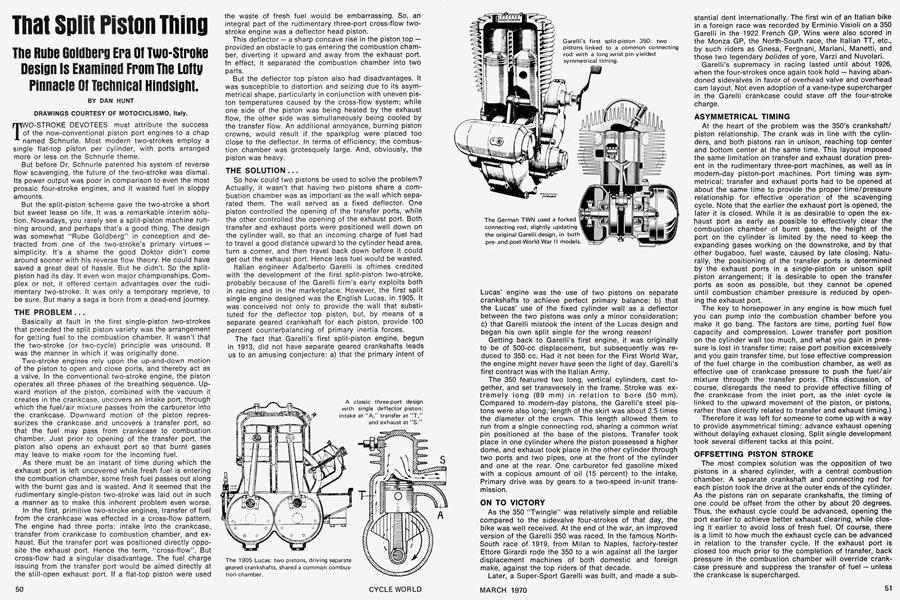
Italian engineer Adalberto Garelli is oftimes credited with the development of the first split-piston two-stroke, probably because of the Garelli firm’s early exploits both in racing and in the marketplace. However, the first split single engine designed was the English Lucas, in 1905. It was conceived not only to provide the wall that substituted for the deflector top piston, but, by means of a separate geared crankshaft for each piston, provide 100 percent counterbalancing of primary inertia forces.
The fact that Garelli’s first split-piston engine, begun in 1913, did not have separate geared crankshafts leads us to an amusing conjecture: a) that the primary intent of Lucas’ engine was the use of two pistons on separate crankshafts to achieve perfect primary balance; b) that the Lucas’ use of the fixed cylinder wall as a deflector between the two pistons was only a minor consideration; c) that Garelli mistook the intent of the Lucas design and began his own split single for the wrong reason!
Getting back to Garelli’s first engine, it was originally to be of 500-cc displacement, but subsequently was reduced to 350 cc. Had it not been for the First World War, the engine might never have seen the light of day. Garelli’s first contract was with the Italian Army.
The 350 featured two long, vertical cylinders, cast together, and set transversely in the frame. Stroke was extremely long (89 mm) in relation to bore (50 mm). Compared to modern-day pistons, the Garelli’s steel pistons were also long; length of the skirt was about 2.5 times the diameter of the crown. This length allowed them to run from a single connecting rod, sharing a common wrist pin positioned at the base of the pistons. Transfer took place in one cylinder where the piston possessed a higher dome, and exhaust took place in the other cylinder through two ports and two pipes, one at the front of the cylinder and one at the rear. One carburetor fed gasoline mixed with a copious amount of oil (15 percent) to the intake. Primary drive was by gears to a two-speed in-unit transmission.
ON TO VICTORY
As the 350 “Twingle” was relatively simple and reliable compared to the sidevalve four-strokes of that day, the bike was well received. At the end of the war, an improved version of the Garelli 350 was raced. In the famous NorthSouth race of 1919, from Milan to Naples, factory-tester Ettore Girardi rode the 350 to a win against all the larger displacement machines of both domestic and foreign make, against the top riders of that decade.
Later, a Super-Sport Garelli was built, and made a substantial dent internationally. The first win of an Italian bike in a foreign race was recorded by Erminio Visioli on a 350 Garelli in the 1922 French GP. Wins were also scored in the Monza GP, the North-South race, the Italian TT, etc., by such riders as Gnesa, Fergnani, Mariani, Manetti, and those two legendary bolides of yore, Varzi and Nuvolari.
Garelli’s supremacy in racing lasted until about 1926, when the four-strokes once again took hold — having abandoned sidevalves in favor of overhead valve and overhead cam layout. Not even adoption of a vane-type supercharger in the Garelli crankcase could stave off the four-stroke charge.
ASYMMETRICAL TIMING
At the heart of the problem was the 350’s crankshaft/ piston relationship. The crank was in line with the cylinders, and both pistons ran in unison, reaching top center and bottom center at the same time. This layout imposed the same limitation on transfer and exhaust duration present in the rudimentary three-port machines, as well as in modern-day piston-port machines. Port timing was symmetrical; transfer and exhaust ports had to be opened at about the same time to provide the proper time/pressure relationship for effective operation of the scavenging cycle. Note that the earlier the exhaust port is opened, the later it is closed. While it is as desirable to open the exhaust port as early as possible to effectively clear the combustion chamber of burnt gases, the height of the port on the cylinder is limited by the need to keep the expanding gases working on the downstroke, and by that other bugaboo, fuel waste, caused by late closing. Naturally, the positioning of the transfer ports is determined by the exhaust ports in a single-piston or unison split piston arrangement; it is desirable to open the transfer ports as soon as possible, but they cannot be opened until combustion chamber pressure is reduced by opening the exhaust port.
The key to horsepower in any engine is how much fuel you can pump into the combustion chamber before you. make it go bang. The factors are time, porting fuel flow capacity and compression. Lower transfer port position on the cylinder wall too much, and what you gain in pressure is lost in transfer time; raise port position excessively and you gain transfer time, but lose effective compression of the fuel charge in the combustion chamber, as well as effective use of crankcase pressure to push the fuel/air mixture through the transfer ports. (This discussion, of course, disregards the need to provide effective filling of fhe crankcase from the inlet port, as the inlet cycle is linked to the upward movement of the piston, or pistons, rather than directly related to transfer and exhaust timing.)
Therefore it was left for someone to come up with a way to provide asymmetrical timing: advance exhaust opening without delaying exhaust closing. Split single development took several different tacks at this point.
OFFSETTING PISTON STROKE
The most complex solution was the opposition of two pistons in a shared cylinder, with a central combustion chamber. A separate crankshaft and connecting rod for each piston took the drive at the outer ends of the cylinder. As the pistons ran on separate crankshafts, the timing of one could be offset from the other by about 20 degrees. Thus, the exhaust cycle could be advanced, opening the port earlier to achieve better exhaust clearing, while closing it earlier to avoid loss of fresh fuel. Of course, there is a limit to how much the exhaust cycle can be advanced in relation to the transfer cycle. If the exhaust port is closed too much prior to the completion of transfer, back pressure in the combustion chamber will override crankcase pressure and suppress the transfer of fuel — unless the crankcase is supercharged.
It is interesting to note that asymmetric timing could also have been achieved in the 1905 Lucas engine, but the old boy apparently missed the boat. At any rate, the mechanical complexity of a dual-crankshaft split piston engine would have prevented it from catching on.
But simpler methods of obtaining asymmetrical exhaust timing were tried. Of these, the Austrian Puch SF engine, extensively produced in the ’30s, seemed the most successful. The British Trojan engine followed a similar scheme.
The Puch S4, a 250, was laid out with the two cylinders in parallel, as in the Garelli. But the crankshaft center line, rather than being parallel with the cylinders, was set transversely. In the Puch a single connecting rod with a U-shaped fork linked the pistons to the crankshaft. In the Trojan, each piston had its own connecting rod, but both were tied to a common crankshaft throw. Either way, the result is the same: connecting rod angularity is achieved faster on the exhaust piston during the downstroke than on the transfer piston, so the exhaust port may open earlier. On the upstroke, the exhaust piston precedes the transfer piston and therefore closes earlier, x
The S4 had a slight drawback in that the cylinders had to be set transversely to the cycle frame for cooling purposes. As the crankshaft rotated in line with the frame, a bevel gear coupling was needed if final drive by chain to the rear wheel was to be used. In a new design in 1935, Puch eliminated this complexity by bringing the crankshaft back in line with the cylinders, giving each piston its own connecting rod and crankshaft throw, but offsetting the throws. The split single could still be set transversely in the frame for optimum cooling, but the direction of the primary drive did not have to be changed. As each piston had its own crankshaft throw, the exhaust cycle could precede the transfer cycle by the chosen amount, which was 15 degrees.
While these engines proved reliable and economical, an inherent design feature would limit their usefulness in high performance application. Namely, the two pistons could not reach top dead center at the same time. So the combustion chamber had to remain unduly large, and it was therefore impossible to obtain a high compression ratio.
THE LAST GASP
But, in the years 1931 to 1934, a German engineer, Zoller, adopted a practice common in the design of radial airplane engines to his own ends — building racing motorcycles. It consisted of making the big'end of one of the connecting rods rotate eccentrically by tying it to the other connecting rod rather than to the throw. Both pistons could reach TDC simultaneously, allowing a small combustion chamber, yet retaining asymmetrical timing. The stroke of the short rod piston would be reduced slightly, as its big end does not trace a full circle with each crankshaft rotation, but a displaced oval. The difference was insignificant.
The Zoller system enjoyed an extended period of success until 1957. Puch used it in the popular TF 250, built after World War II. At DKW in Germany, where Zoller headed the racing department for several years, several Grand Prix racing engines following this scheme were built between 1935 and 1939. The Italian ISO factory used similar engines in bikes and scooters, and in the Isetta mini-car, until the mid-fifties.
Those DKW Grand Prix engines were quite complex. They were all water-cooled, with cylinders set in line with the frame. The first was supercharged by a piston pump set horizontally in front of the crankcase at 90 degrees from the other two cylinders. Bore/stroke of the rear cylinder was 47.5 mm by 69.7 mm, while the front was 47.5 mm by 70.5 mm, for a displacement of 453 cc. The piston pump supercharger, with 40-mm bore and 120-mm stroke, sucked through an elastic diaphragm which acted as an automatic valve. The asymmetric timing prevented fresh gas losses and considerably aided the supercharging effect.
In 1938, DKW built another GP engine, this time displacing 250 cc. It was of similar design, but the supercharger was set vertically in front of the two cylinders and the inlet was controlled by a cylindrical rotor, set horizontally and transversely to the frame, and fed by two carburetors. The engine developed more than 30 bhp at the crankshaft, and pushed the racing bike along at about 110 mph, very fast for a two-fifty of those days. The machine won two European championships, equivalent to the present FIM world championships, for German rider Ewald Kluge, in 1938 and 1939. Kluge also won the Isle of Man 250-cc TT in 1938 at record speeds.
Then came the war, which interrupted development of a third type of DKW racing engine, with a vane-type Zoller supercharger placed in front of the crankcase. After the war, the FIM banned superchanging. The move effectively killed the racing value of the split-piston two-stroke, as they could not be made competitive against the fourstrokes without supercharging.
When Dr. Schnurle conceived the reverse flow scavenging principle, the final blow was dealt. The split-piston engine was obsolete.
BACK TO SINGLE PISTONS
Schnurle was able to use a compact, single flat top piston in his design. By locating two or more transfer ports just off to the side of the exhaust port, and directing fhe transfer stream away from the exhaust port, he was able to achieve excellent cylinder evacuation and filling with relatively little fuel waste. Further, use of a single flat top piston meant the combustion chamber could be tight and compact, producing a very high compression ratio. Greater power output resulted, even with symmetrical timing. Temperatures were more even throughout, so less distortion would result. The piston itself could be made stronger, and lighter and it had no undue rises or sharp edges to produce hot spots.
But the main reason for the success of the Schnurle scheme was that it allowed short stroke, as the high wall barrier was no longer needed. Unlike the cumbersome split-piston engine, which of necessity was a long-stroke machine, the compact reverse-flow design could be turned at much higher rpm. When Kadenacy discovered that exhaust waves at high rpm could be made to create sub-atmospheric pressure in the combustion chamber, which would intensify cylinder filling, the split-piston game was truly over.
The new engine was simpler, more reliable, and more powerful. It could even compete with four-strokes on their own terms — unsupercharged. And so ended a complex saga. Simplicity had dealt the final blow.